Win3mu - Part 3 - The CPU
This is Part 3 in a series of articles about building Win3mu — a 16-bit Windows 3 emulator. If you haven’t done so already I recommend starting at the beginning where I explain my (ir)rationale for starting this project.
This post covers the design of the CPU.
At the center of any emulator is an accurate emulation of the CPU and it’s usually the first thing to tackle. Win3mu’s CPU is implemented in a separate project called “Sharp86”.
Instruction Set
Initially I was planning on implementing just the 8086 instruction set and running Windows in real-mode. It didn’t take long to realize however that that protected mode solves a whole class of memory management issues (which I’ll explain in a later article) so Sharp86 implements the 80186 instruction set and a mechanism to implement protected mode features externally to the processor.
Since all the new instructions introduced between the 186 and 286 are related to protected mode, from the 16-bit program’s point of view the CPU might as well be a 286 – because it shouldn’t be using any protected mode instructions anyway.
The ALU Class
The Arithmetic Logic Unit, aka the ALU, is the part of the processor that performs math and logic operations. It accepts one or two input values, performs an operation, provides the result and sets the flags register according to the results.
Sharp86's ALU is implemented as a base class to the main processor and includes methods for all the required operations — most in 8 and 16-bit forms:
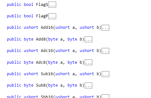
It also implements the flags register and as a slight performance tweak it delays resolving some flags until required. eg: very rarely is the parity flag used so it doesn’t calculate it unless it’s read.
The CPU Class
The CPU class derives from the ALU class and implements most of the processor logic. It’s responsible for maintaining the rest of the registers, instruction decoding, memory and I/O port access and raising interrupts.
It communicates with the outside world via an IBus interface which is analogous to the system bus on a physical processor. For simplicity, it’s a an 8-bit data bus (unlike a real 286 which is 16-bit).
public interface IBus
{
    byte ReadByte(ushort seg, ushort offset);
    void WriteByte(ushort seg, ushort offset, byte value);
    ushort ReadPortWord(ushort port);
    void WritePortWord(ushort port, ushort value);
    bool IsExecutableSelector(ushort seg);
}
The CPU class consists of a few key parts:
- A huge switch statement that reads one instruction opcode, decodes it and performs the appropriate operation — often by prodding the ALU to do something.
- Handling of the 8086 Mod Reg R/M addressing modes.
- Interrupt and exception handling – see below.
Besides IBus and a set of properties to access the registers, the API to the processor really only consists of a single method Step() which executes one instruction and returns.
By calling Step repeatedly in a loop you have a running processor:
// Create a CPU
_cpu = new CPU();

// Setup the memory bus
_cpu.Bus = _memoryHeap;

// Setup some registers
_cpu.cs = 0x10;
_cpu.ip = 0x100;
_cpu.ax = whatever;

// Run!
while (_shouldContinue)
{
    _cpu.Step();
}
Interrupts and Exceptions
x86 processors have three ways that interrupts are raised. In Sharp86 these all end up at the CPU’s RaiseInterrupt method
- Hardware Interrupts – a hardware interrupt can be emulated by calling the
RaiseInterruptmethod from outside the processor between calls toStep(). Win3mu doesn’t use hardware interrupts at all. - Software Interrupts – Sharp86 automatically calls
RaiseInterruptwhen anintinstruction is executed - Exception Interrupts – these are raised when the processor detects an exception. Sharp86 catches any C# exception of type
CPUExceptionthrown during a call toStep()and callsRaiseInterrupt. eg: if the emulator’sIBusimplementation throws aGeneralProtectionFaultExceptionin itsWriteBytemethod then this would cause interrupt 13 to be raised.
The default RaiseInterrupt method does the same as a real processor – it looks up the interrupt descriptor table for the address of the handler function, pushes the Flags registers and performs a far call to the handler.
Note that RaiseInterrupt doesn’t actually run the interrupt handler — it just sets up the processor so that next time Step() is called it will be.
CPU Bugs Are Nasty!
I’m a little paranoid about bugs in a processor. Here’s why…
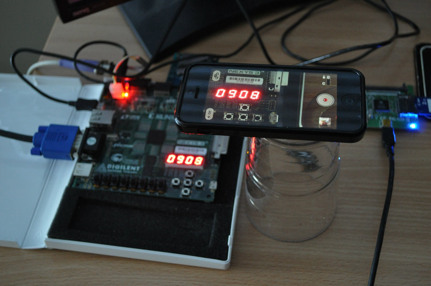
When I was working on FPGABee I hit a problem where the operating system was hanging part way through boot. Since the FPGA board I was using had very limited debugging support I didn’t have much visibility into what was happening — I couldn’t even step through the code.
In the end I configured the circuit to show the current instruction pointer on the LED readout, slowed the clock speed right down, videoed it with my iPhone and then played it in slow motion while stepping through a disassembly listing. I spent a lot of time tracking down what turned out to be a bug in the processor core— it wasn’t incrementing a register during a string operation.
If there’s one thing I learned from this its that you need to be able to trust the processor — CPU bugs can be super nasty to chase down.
I don’t expect to be doing video camera debugging with this project but a subtle processor bug popping up in the middle of a program would probably be very difficult to track down.
Time for a whole pile of unit tests…
Unit Testing
Testing a processor is tricky. It’s nearly impossible to get full coverage so I broke it down into a few key areas:
- The ALU — tests for every operations and important flags after each
- The Mod Reg R/M Decoding — tests one instruction with all the different addressing modes.
- Instruction Decoding — at least one unit test for each instruction.
For the instruction decoding tests I wanted to make sure I had the right opcode mapped to the right instruction so I used a real assembler (YASM) to generate one instruction which then gets tested. Each of these unit tests follows this pattern:
- Set the CPU’s registers through it’s public properties and/or write values to to emulated memory
- Invoke YASM to assemble one instruction and load the generated code into emulated memory
- Step the CPU
- Check the results
[TestMethod]
public void Adc_Eb_Gb()
{
    WriteByte(0, 100, 40);
    FlagC = true;
    al = 20;
    emit("adc byte [100], al");
    run();
    Assert.AreEqual(ReadByte(0, 100), 61);
}
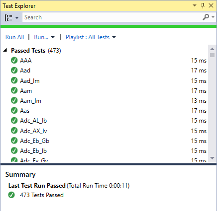
All up, there are over 470 test cases and so far I’ve only noticed one bug that’s slipped through — a far call instruction that was incorrectly doing a near call.
First Signs of Life
For the processor’s first test run I needed a really simple executable. Since you can’t get much simpler than a DOS “.com” file I decided to:
- Write a simple C# console program that uses Sharp86 and implements just one DOS
Int 21hfunction—09houtput string. It then loads and runs a .com file. - Wrote a simple .com program and compiled it with YASM.
- Ran it on DOSBox and under Sharp86 and checked for the same output.
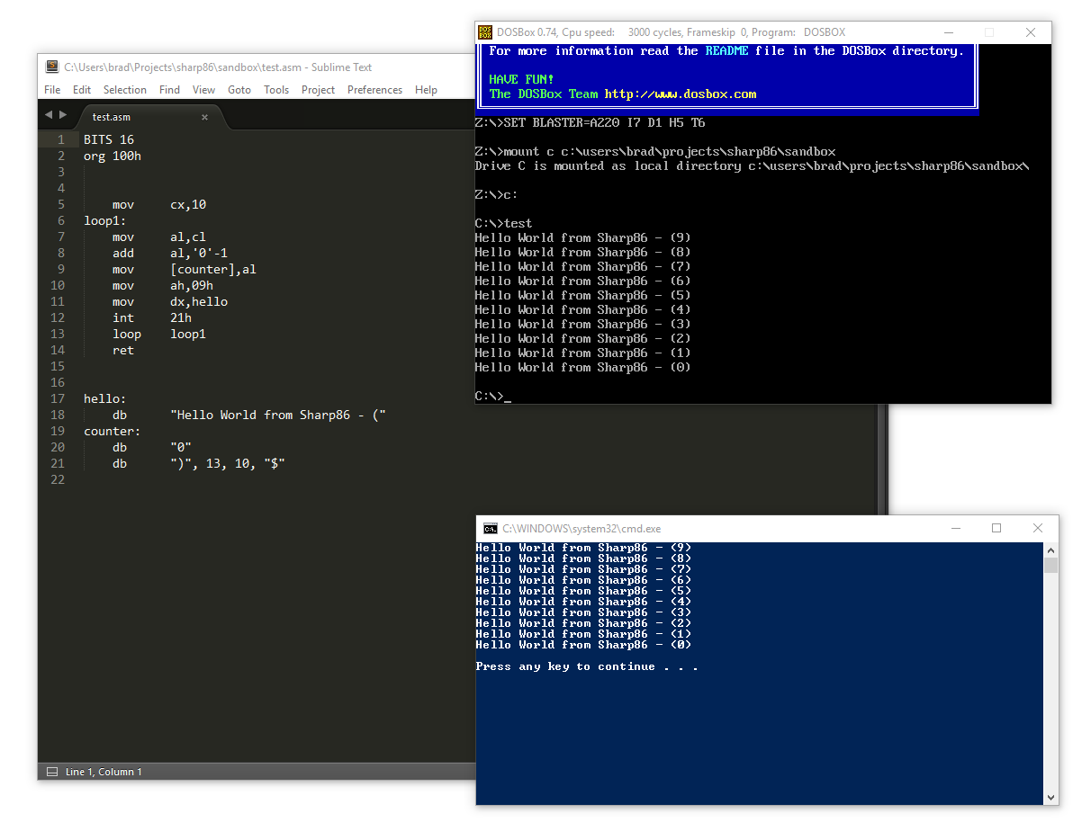
I ran a few more ad-hoc tests after which I was fairly confident I had a working processor.
Cycle Accurate
Often you’ll hear the term “Cycle Accurate” when talking about CPU emulations. Sharp86 is not cycle accurate since it doesn’t need to be but I thought I quickly describe what this means.
For a hardware based emulation such as a an FPGA based processor, cycle accurate really means cycle accurate — it means the timing and order of CPU’s control lines, address and data bus and the speed of instructions all match the original processor.
For a software based CPU emulation it’s a little different and more about trying to accurately match the execution speed of the original processor.
This is normally done by calculating the number of clock cycles each instruction took on the original processor and maintaining a running count of which clock cycle number the emulated processor is up to.
The number of clock cycles per instruction is usually variable — and can even depend on the results of an operation. eg: conditional jump instructions often take a different number of clock cycles depending whether the branch was taken or not.
Once you have that running cycle count it’s pretty easy to throttle the processor to match the speed of the original:
- Use the current system time to calculate the expected current cycle number
- Process instructions until the current cycle number catches up to the calculated expectation
- Yield, or go do something else for a while (eg: update the screen).
- Repeat from 1
As mentioned, this project doesn’t need this and simply executes as fast as possible. Programs running under the emulator will be scheduled by Windows just like any other program.
Pseudo-Protected Mode
I’ve mentioned pseudo-protected mode a couple of times now but this article is long enough so I’ll leave it and cover it in the next post.