TRS-80 in an FPGA - Virtual Cassette Player
Building a virtual TRS-80 cassette player that reads binary .cas files from an SD card and renders an audio stream representing a tape recording of that data.
"Big-80" is an implementation of a TRS-80 Model 1 in an FPGA. This post describes the virtual cassette player that reads binary .cas files from an SD card and renders an audio stream representing a tape recording of that data.
Background
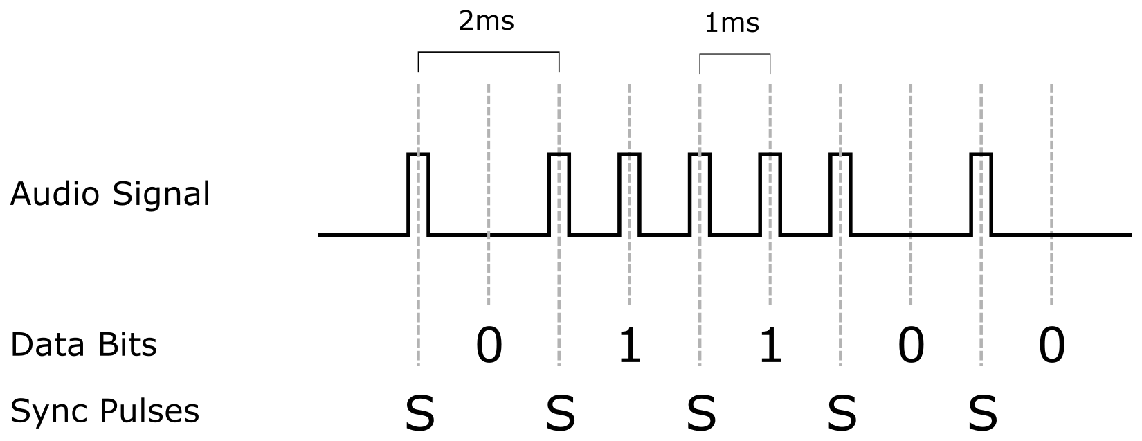
The TRS-80 audio cassette format is very simple:
- Every 2ms (ie: 500 times/second aka 500baud) there's a synchronization pulse.
- In between each sync pulse there's another pulse for a 1 bit and no pulse for a zero bit.
- Data bytes aren't wrapping in packets - no start/stop bits nor parity bits.
- Bits are transmitted MSB first
Side note: for this project I'm treating the audio signals as a single bit value - ie: a zero volt and a positive voltage level. In practice I'm pretty sure the TRS-80 could also produce a negative voltage and the actual pulses consisted of a positive pulse followed immediately by a negative pulse.
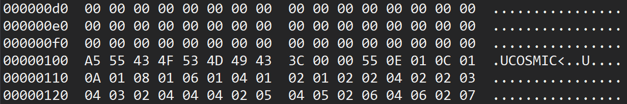
In order to synchronize to the first byte, each tape recording starts with a series of zero bytes, followed by an 0xA5 byte (ie: binary 10100101). Those initial 1 bits let the listener synchronize to the rest of the data stream.
Although the audio protocol doesn't include any parity or data checks, the binary tape format divides the data into blocks of 256 bytes each with a checksum so errors can be detected.
Cassette Audio Renderer
The Trs80CassetterRenderer component (source code) renders one byte of data at a time to an audio stream in the above format. It does this by:
- Maintaining a counter that tracks a 2ms period and then restarts.
- When the counter is within the sync pulse region output a 1.
- When the counter is within the data pulse region output the most significant bit of the current data byte.
- When the counter is at any other position output a 0.
- Two clock ticks before the counter wraps, if all 8 bits have been rendered, assert an external signal indicating that the next byte is needed.
- One click tick before the counter wraps, if all 8 bits have been rendered read the next byte from input, otherwise shift the current byte one bit to the left.
The values output in steps 2 to 3 will become the audio signal that will be fed into the TRS-80's cassette input.
Note that the renderer doesn't have start or stop controls - instead the reset signal is held high to stop it.
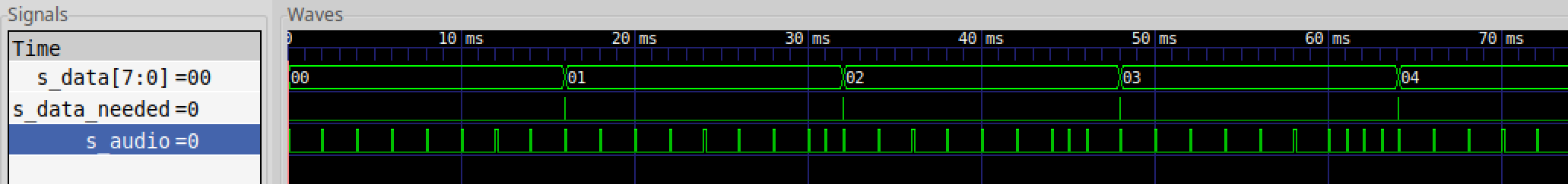
Testing the Audio Renderer
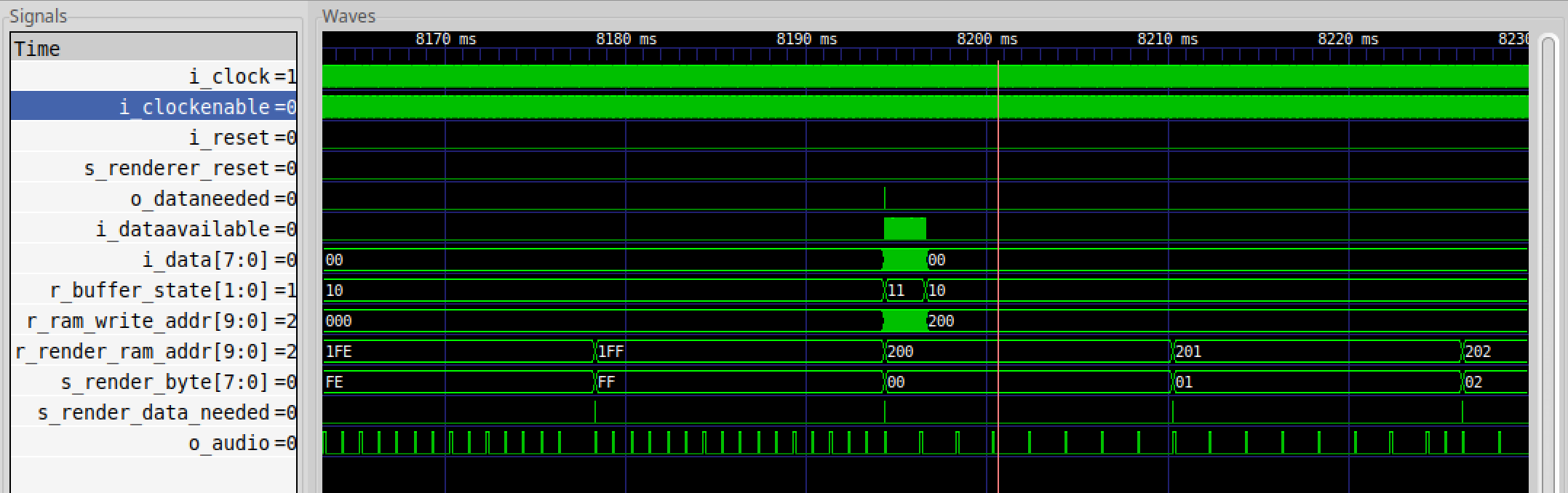
Here's a simulation run (source code) of the audio renderer in which you can easily see the current byte, the "data needed" pulses and the rendered audio.
Supplying a Constant Stream of Bytes
When ever the renderer indicates that it needs the next byte of data, that data needs to be available on the very next clock cycle.
The data will be read from an SD card and in order to keep up a constant supply the Trs80CassetteStreamer component (source code) maintains a 1024 byte buffer. Each block on an SD card is 512 bytes so that the audio renderer can be reading from one half while the SD card is filling up the other.
- When the streamer needs more data (either at the start of the rendering, or because one half of the buffer has been drained), it raises a "data needed" signal.
- After raising the data needed signal it expects its incoming "data available" signal to be asserted exactly 512 times and each time for a byte of data to be available on its data input.
- At the start of the rendering (ie: after the reset signal has been released) the streamer requests the first block of data while keeping the audio renderer in a reset state.
- Once the first block is loaded, the audio renderer is released.
Like the renderer, the streamer runs indefinitely but can be stopped by holding the reset signal high.
Testing the Audio Streamer
The audio streamer was also tested in the simulator (source code).
Since I wanted to test both loading the initial two data blocks and loading the third data block once the first block had been drained, I needed a very long simulation run - loading from cassette is slow. Simulating 8.5 seconds took about 25 minutes and resulted in a 2.5Gb signal trace.
SD Card Controller
I'm not going to cover the SDCardController (source code) in detail here. I lifted this from FPGABee and only made some minor changes.
The SD Controller works with standard SD cards and SDHC cards. It provides a simple interface where a client can set a block number, issue a read or write command and the controller then expects data to be available (for writes) or provides data as it's loaded (for reads).
Virtual Cassette Player
The Trs80CassettePlayer component (source code) ties all of the above together:
- It maps "data needed" requests from the streamer to SD card commands to initiate a read.
- Data from the SD card is provided to the streamer as it becomes available.
- It holds the streamer in a reset state when not playing.
- Has a button input signal to start and stop playing.
- Has button input signals to select next and previous tape.
In order for this to work, the SD card has to be specially formatted since there's no "file-system" as such. Instead each "tape" starts on a 32-block boundary (ie: 16kb) and the cassette player has buttons to select the next/previous tape. The currently selected tape is shown on the Mimas V2's seven-segment LED display. For more, see the instructions on how to prepare the SD card.
Testing the Completed Virtual Cassette Player
To test this (source code) the output of the cassette player was connected to the Mimas V2's audio output jack which was then recorded on a PC in Audacity where it could be inspected.
#trs80 virtual cassette file player in #fpga reading from SD card and rendering audio. No file system on SD card so each “tape” starts on a 16k boundary. Up/down buttons to select tape. For my holiday hacking project building a TRS80 Model 1 in an fpga. #z80 #retrocomputing pic.twitter.com/w6D5szJ1KG
— Brad Robinson (@toptensoftware) December 27, 2019
It took a few goes to get this working - primarily because of timing differences between with the SD card and how I simulated data streaming in the prior tests. The first two data blocks are loaded one immediately after the other however the SD Controller stays busy for a short period after each read and the second read command was getting ignored, thus skipping one block.
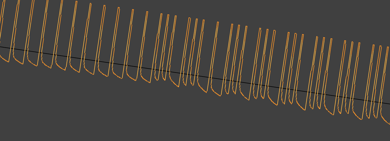
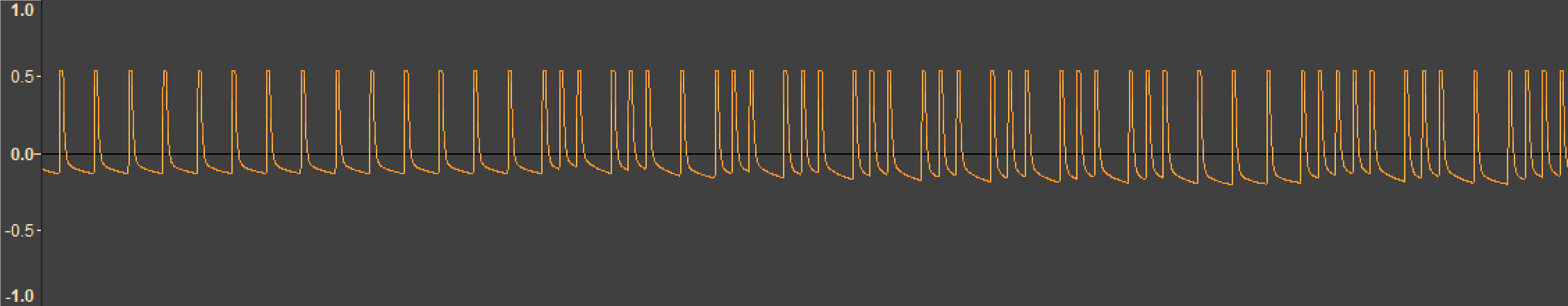
Here's a close up of the recorded audio - if you look carefully you can make out the 0xA5 sync-byte.
To double check everything was correct, a recording was played back into PC based TRS-80 emulator - and it loaded fine!
I don't have a way to confirm this but I think you could feed the output of this test project into a real TRS-80 and it would work.
A Final Note
I didn't mention this above, but all of the cassette audio rendering logic is driven by the same 1.774MHz clock that will be driving the CPU. This is a little trick I figured out when working on FPGABee: by using the same clock source for the CPU and the audio rendering you can overclock it and get really fast tape loads. (But that's for later).
Stay tuned, in the next post I'll pull all this together and make a working TRS-80!
Have thoughts on this? Leave a comment on Twitter.