TRS-80 in an FPGA - Keyboard Controller
Implementing the keyboard controller for a "Big-80" - a TRS-80 in an FPGA.
"Big-80" is an implementation of a TRS-80 Model 1 in an FPGA. This post describes the keyboard controller which processes keys through 4 simple but distinct stages.
Background
The TRS-80 maps keyboard switch states into a range of memory addresses which when read, have particular bits set for particular keys.
The Mimas V2 FPGA board that I'm using for this project doesn't have a way to directly connect a keyboard, however a Digilent Pmod PS2 makes it fairly simple to add one.
For this project, the FPGA communicates with the PS2 keyboard and maps the generated events into the memory mapped bits expected by the TRS-80.
PS2 Serial Communications
The PS2 interface uses a bi-directional serial communication interface. Only keyboard input is needed for this projects so it's treated as omni-directional interface (there's no need to write to the keyboard to set key repeat rates or control the indicator LED states).
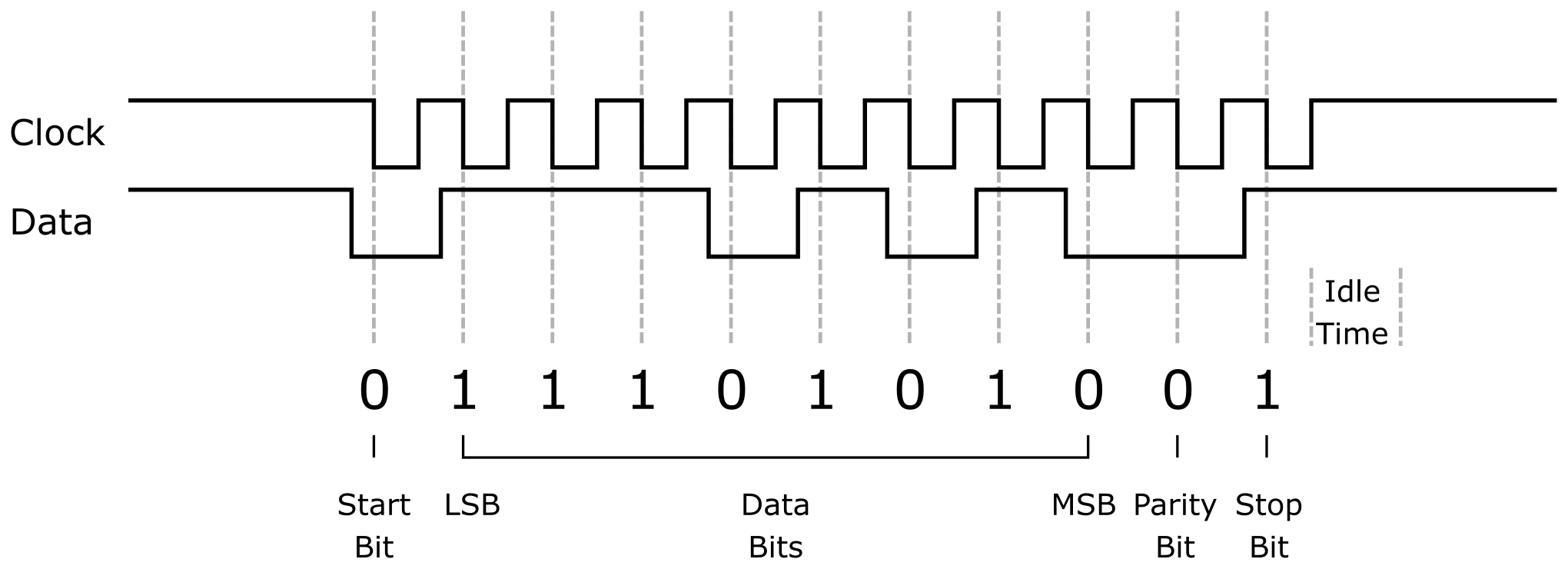
The main two signals from the keyboard consist of a clock and data signal. The clock signal is held high by the keyboard when idle. When transmitting, the clock signal toggles and on each falling edge a single bit of data is available on the data signal.
Each transmission is a single byte enclosed in an 11 bit packet consisting of a '0' start bit, the 8 data bits (MSB first), a parity bit and a '1' stop bit. The parity bit is odd parity - meaning that between it and the 8 data bits the total number of 1 bits is odd.
The PS2Input component (source code) implements the listener for the PS2 protocol, first pushing the received bits through an 11-bit shift register.
Instead of counting 11 bits and risking getting out of sync, the end of each packet is detected by monitoring for the clock signal becoming idle and the last 11 received bits are used. It's considered idle when there is no activity for the period of one full clock cycle. Since the PS2 clock is typically between 10 and 17 KHz the longest possible clock period is 100us.
Once the idle period is detected, an outgoing "data available" signal is asserted for one system clock cycle along with an error flag if there was a parity mismatch.
Some further notes:
- Since the incoming PS2 clock signal is asynchronous to the system clock, it needs to be re-synchronized it by registering the signal through a flip-flop (ie: delaying it one clock cycle)
- A de-bounce filter is used on the re-synchronized PS2 clock signal to ensure it's stable for 5us before accepting it as an valid transition edge. This avoids problems caused by cross-talk, ensures a clean clock signal and that it doesn't get out of sync during the transmission should the signal bounce.
- The PS2 data signal is not synchronized nor de-bounced since the data signal is supposed to be stable before the falling edge of the clock anyway.
Decoding Keyboard Bytes into Events
So what are the actual bytes that the keyboard sends? The protocol is pretty simple:
- If the high bit of the received byte isn't set then it's the scan code of a key that was pressed.
- If the received byte is 0xF0 then the next received scan code represents a key being released instead of a key being pressed.
- If the received byte is 0xE0 then the next received scan code is an extended scan code.
- Any other byte should be ignored and any pending "release" or "extended" flags should be cleared.
The PCKeyboardDecoder component (source code) receives incoming bytes from the PS2 keyboard and generates key events that indicate the scan code, an extended key code flag, a key release flag and a flag indicating that data is available.
Testing the PS2 Keyboard Input
The PS2 keyboard handling was tested using a simple test project (source code) that displays the most recently received scan code on the Mimas V2's seven segment display.
The right most 2 digits show the hex scan code, the left most digit displays "1" if it's an extended key code and any key release event clears the display back to "000".
Here's a tweet I posted showing this working:
PS2 keyboard interface in fpga working, showing scan codes on the 7-segment. This is for my holiday project, a trs80 model 1 in an fpga. Next step will be to map PC scan codes to TRS80 keyboard memory addresses. #z80 #trs80 #fpga #RetroGaming pic.twitter.com/puhVX7Bujl
— Brad Robinson (@toptensoftware) December 24, 2019
Mapping Keyboard Events to Keyboard State
In order to implement the TRS-80's memory mapped keyboard , the current state of every relevant key key needs to be known:
- Maintain a bit array to store which keys are pressed. (Not every PC key is stored in the bit array - only those that are used by the TRS-80)
- On receiving a key event from the PC keyboard decoder, set or clear the corresponding bit in the array for that key.
From this key state array the state of all 64 of the TRS-80's key switches can now be generated using simple combinatorial logic. This is mostly a one-to-one mapping, but not quite. For example the left and right shift keys are tracked separately, but if either is pressed then the TRS-80 shift key is reported as pressed.
This is all done by the Trs80KeySwitches component (source code).
This mapping will get more complicated when I implement "typing mode" (see below).
Implementing the TRS-80 Keyboard Memory Map
The table below shows how each key is mapped in the TRS-80 keyboard memory map. For example while the B key is pressed, the byte read from address 0x3801 will have bit 2 set.
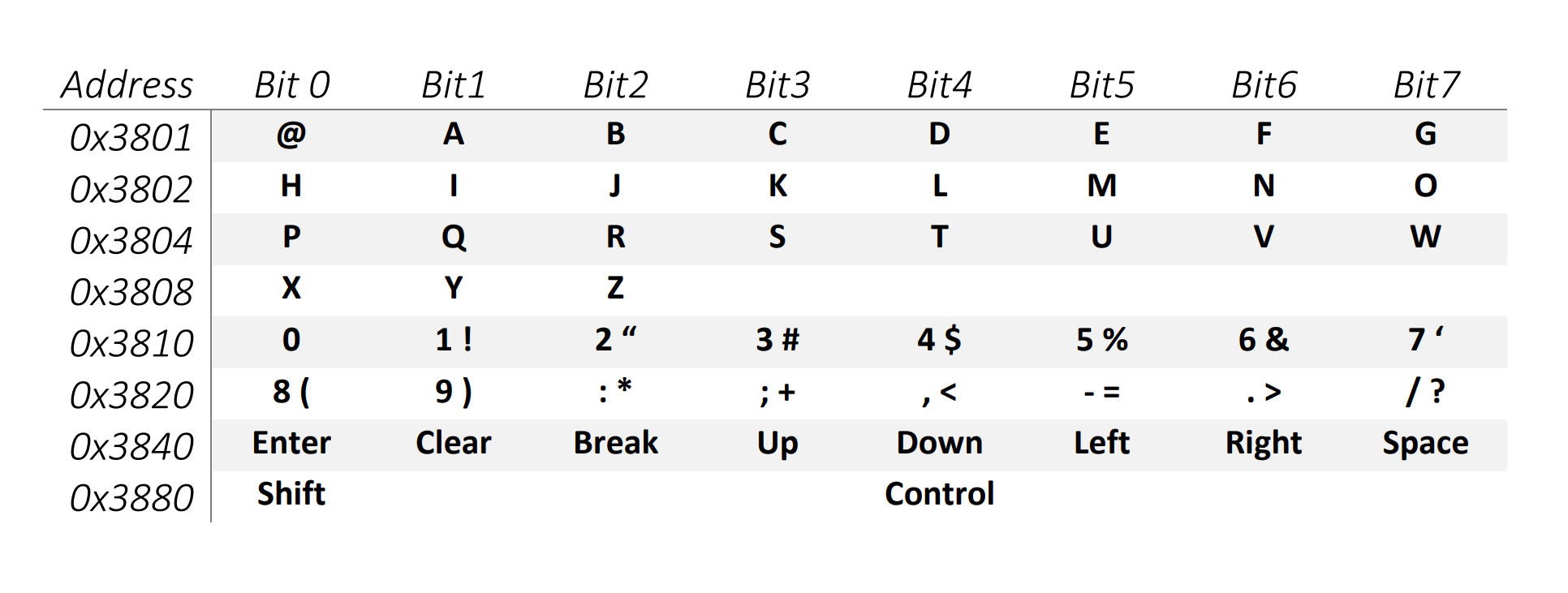
Also, the addresses can be ORed together to read multiple rows at once. eg: if you OR together 0x3801 and 0x3804 and read from address 0x3805 and either B or R was pressed, then the returned byte will have bit 2 set.
The Trs80KeyMemoryMap component implements this (source code) accepting 8 address lines returning the mapped key states for that address.
Testing the Complete TRS-80 Keyboard Controller
To test the entire keyboard decoding and mapping I created a project (source code) that uses the 8 DIP switches on the Mimas V2 to select the address lines and the 8 segment LED strip to show what's returned for that memory address.
Then it was just a matter of going through every key and making sure they were all mapped correctly, like this:
Now working - fpga decoding PC keyboard scan codes to TRS80 memory map bits. It’s hard to see but the dip switches select the address lines and the led strip shows the set bits at that address. #fpga #z80 #trs80 pic.twitter.com/KTtQ6JdPLu
— Brad Robinson (@toptensoftware) December 24, 2019
Typing Mode
Currently I've only implemented a topographical key mapping where each TRS-80 key is mapped to a similar position on the PC keyboard. This works well when the physical layout is important (perhaps games where keys are used for navigation), but not so well for typing.
For example, the shifted numbers on the TRS-80 keyboard produces mostly different characters to what's shown on a PC keyboard.
I'll definitely address this at some point because it's really hard to remember how to type all those characters, but for now it's good enough.
Stay tuned, implementing a virtual cassette player is next.
Have thoughts on this? Leave a comment on Twitter.