FPGA Signal Reflector
Experiments in using a serial UART port connection to reflect signal values between an FPGA and a connected PC.
Recently I've been trying to improve my FPGA development skills and part of that involves finding better ways to diagnose issues. One capability I'd never really used before is serial UART communication with a connected PC. This post covers a technique I've been working on that lets you reflect a set of signals from an FPGA back to a connected PC - and vice versa.
In the past I've often used an FPGA board's LEDs and 7-segment displays for debugging purposes. Perhaps I'd show an address or light-up an LED if a particular state gets hit. While this works, it's tedious and often requires re-jigging on-board resources that might already be used for something else.
A serial port is a handy way to communicate with an FPGA since it only requires a single wire for each direction and most boards already have some form of built-in serial connection that will let you communicate with the FPGA using the same USB connection as used for programming the board.
Introducing Reflector
"Reflector" is a component I've developed that let you "reflect" a set of signals on the FPGA back to the PC - and vice versa. The project includes the VHDL components that sit on the FPGA and a small Node.js library that makes it easy to write scripts that receive those signals and send signals back to the FPGA.
While this might sound a bit like a logic analyzer, it is most definitely not and was never intended to be. The serial port is not fast enough to support real-time transmission of every signal change. Rather this should be considered an alternative to UI elements on the FPGA board - a replacement for using for LEDs, 7-segment displays, push-buttons, switches etc...
This approach offers some nice advantages over physical UI elements. For example, you can have an unlimited number of display elements letting you show long hex digits and lots of LED like indicators. You can also programmatically control the device and it even supports writing a .vcd file so you can see signals change over time in a wave viewer (eg: GtkWave) - admittedly at a much lower time resolution than what a simulator or logic analyzer gives.
Think of Reflector as an extension to the FPGA board that gives an unlimited number of LEDs, 7-segment elements, push buttons and switches that can easily be reconfigured and automated to suit your needs.
The ReflectorTx Component
The FPGA side of Reflector consists of two main components, one for sending and one for receiving - you can use either or both depending on your needs.
The ReflectorTx component takes a variable number of signals (configured by the p_bit_width generic parameter) and sends them serially to a listening PC.
Connect any signals you want to monitor to the i_signals port and ReflectorTx will send a packet (via o_uart_tx) when any of the signal values change.
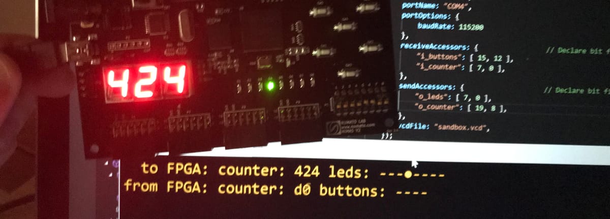
In the following example I'm sending a 16-bit packet with the state of 4 active-low push buttons in the top 4 bits, and an 8-bit counter in the lower bits. (4 bits are unused and I really should reconfigure it to a 12 bit packet, but it's just an example).
    -- Signals sent to PC.
    s_signals_tx <= (not i_buttons) & "0000" & s_counter;

    -- Reflector component automatically tracks
    -- changes to its input signals and sends them
    -- via uart to the PC as quickly as possible
    reflector_tx : entity work.ReflectorTx
    generic map
    (
        p_clken_hz => 100_000_000,
        p_baud => 115_200,
        p_bit_width => 16
    )
    port map
    (
        i_clock => i_clock_100mhz,
        i_clken => '1',
        i_reset => s_reset,
        o_uart_tx => o_uart_tx,
        i_signals => s_signals_tx
    );
Important: not every signal change will necessarily be sent: if a signal changes while a it's already transmitting, those changes will be sent in a new packet when the current one finishes. However if the signal reverts back to its original value before the current packet finishes sending, that change will be lost and not seen by the listener.
ReflectorRx
The ReflectorRx component does the opposite to ReflectorTx: it listens to a serial connection via i_uart_rx for bit packets and presents them on the o_signals port.
In this example, it's listening for 20 bit packets, with the lower 8-bits being shown on and 8-segment LED strip and the top 12 bits shown in hex on a 3-digit 7-segment display (ie: all the available LEDs on a Mimas V2 board).
    -- Signals received from PC.
    o_leds <= s_signals_rx(7 downto 0);
    s_seven_segment_value <= s_signals_rx(19 downto 8);

    -- ReflectorRx receives signals from PC
    reflector_rx : entity work.ReflectorRx
    generic map
    (
        p_clock_hz => 100_000_000,
        p_baud => 115_200,
        p_bit_width => 20
    )
    port map
    (
        i_clock => i_clock_100mhz,
        i_reset => s_reset,
        i_uart_rx => i_uart_rx,
        o_signals => s_signals_rx
    );
Serial PC Connection
Many FPGA boards have a way to establish a serial UART connection via the same USB port that's used for programming. For the Mimas V2 board I'm using, this is via pins A8 and B8.
NET "i_uart_rx" LOC = A8;
NET "o_uart_tx" LOC = B8;
A couple of things to be aware of if you're using the Mimas V2 board:
- The UCF file supplied by Numato has these pins confusingly named from the perspective of the other device, not the perspective of the FPGA design - so you need to swap the TX/RX.
- If you're using Numato's board firmware you need to use the on-board switch to select UART mode instead of programming mode. I recommend switching to this firmware - it's faster and you don't need to use the switch.
In many cases this built-in connection will work fine however the supported baud rates might be limited. As an alternative you can also use a cheap FTDI module like those used to program Arduino Mini boards.
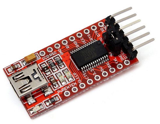
These can often be configured to run at up to 3M baud (though I haven't tested Reflector at this speed). Just make sure you get one with a switch or jumper to switch it to 3.3V mode.
Connect the Ground, TX and/or RX pins to spare pins on the FPGA board and configure those pins in your FPGA project correctly. eg: I use pins 1 and 3 on GPIO connector P8 on the Mimas board:
NET "i_uart_rx" LOC = R11;
NET "o_uart_tx" LOC = R10;
Of course if you don't need bi-directional support you only need to connect either the TX or RX pin as required.
Reflector NodeJS Library
To make the PC side all this easier, there's a Node.js library that handles all the underlying details. Source code is included in the same repository - see here.
Let's break down the example sandbox.js script piece by piece and see how it works.
The main API to the library is the Reflector class which handles the serial communication and provides an easy way to declare property accessors that map directly to specific bit-ranges.
The Reflector class is configured by an options object that is passed to its constructor:
// Reflector establishes the connection with the FPGA over serial port
let reflector = new Reflector({
    receiveBitCount: 16,
    sendBitCount: 21,
    portName: "/dev/ttyACM1",
    portOptions: {
        baudRate: 115200
    },
    receiveAccessors: {                 // Declare bit fields from FPGA
        "i_buttons": [ 15, 12 ],
        "i_counter": [ 7, 0 ],
    },
    sendAccessors: {                    // Declare bit fields to FPGA
        "o_leds": [ 7, 0 ],
        "o_counter": [ 19, 8 ],
    },
    vcdFile: "sandbox.vcd",
});
Here's a quick description of each configuration option:
receiveBitCount- how many bits in incoming bit packets. This must be the same as thep_bit_widthparameter on the transmitting component.sendBitCount- how many bits in outgoing bit packets. Must match the bit width of the receiving component.portName- the name of the serial port the FPGA (or FTDI module) is connected to.portOptions- configuration options for the underlying serial port connection - see here. The VHDL UART components used by Reflector only work with one start bit, one stop bit, no parity bits and no flow control. The baud rate is configurable here but don't forget to update the matching VHDL generic parameters.receiveAccessors- defines a set of additional properties that will added to the Reflector instance that map to specific underlying bit ranges. Notice that the bit ranges shown in the example match the signal mapping in the FPGA design.sendAccessors- same as above but for the sent data.vcdFile- optional, if set a .vcd file will be generated showing all value changes for the session.
Once created the Reflector needs to be opened:
// Open connection
await reflector.open();
Note: this is an async method and should be awaited before continuing. See the example for how to wrap all this in an async function.
We're now all setup for communicating with the FPGA and can update the signals on the FPGA by simply setting the accessor properties we declare above.
eg: this will light up the right most LED if using the example design:
reflector.o_leds = 0x01;
We can also read the current state of signals on the FPGA:
console.log(reflector.i_buttons);
and, get notified whenever any signals on the FPGA change using the Reflector's change event:
reflector.on('change', function() {
    console.log(reflector.i_counter, reflector.i_buttons);
});
Value Formatting Helpers
The accessor functions provide an easy way to get the integer value of the specified bit ranges but there's also some handy formatting functions that will format these values.
formatHex(accessorName)- formats in hex, and pads to just enough digits for the bit width of the accessorformatBinary(accessorName)- same as above but in binaryformatLeds(accessorName)- also formats in binary but replaces the 1's and 0's with Unicode characters that mimic LED indicators.
eg:
console.log(reflector.formatHex('i_counter'));
console.log(reflector.formatLeds('i_buttons'));
Controlling the FPGA
Normally your script will be responding to events to change the signal values.
Here's a simple example that uses a timer to increment the outgoing counter and create a rotating pattern on the LEDs:
let timer = setInterval(function() {

        // Update Counter
        reflector.o_counter++;

        // Rotate LEDs
        reflector.o_leds = ((reflector.o_leds << 1) | (reflector.o_leds >> 7)) & 0xFF;

}, 500);
Console UI
To present a nicer UI, I've also put together a helper component called ReflectorUI that provides a simple non-scrolling console based UI that has a status area at the top of the screen (to display formatted signal values) along with a place to type commands and display command results.
To use it, construct an instance, hook up to the line event to listen for typed commands and call its run() method
let ui = new ReflectorUI();
ui.on('line', function(line) {
    console.log("You typed:", line);
});
await ui.run();
You might use the typed commands to adjust the outgoing signal values for example.
(At some point I'll probably provide and automatic command line handler that will set any accessor value based on typed name - I just haven't had time yet and not sure how useful it will be).
To update the status area, use the showStatus method. eg: here the change event is used to update the status display any time a signal value changes:
reflector.on('change', function() {
        let msg =  `  to FPGA: counter: ${reflector.formatHex("o_counter")} leds: ${reflector.formatLeds("o_leds")}\n`;
            msg += `from FPGA: counter: ${reflector.formatHex("i_counter")} buttons: ${reflector.formatLeds("i_buttons")}`;
        ui.showStatus(msg);
});
Here's how the Reflector UI looks:
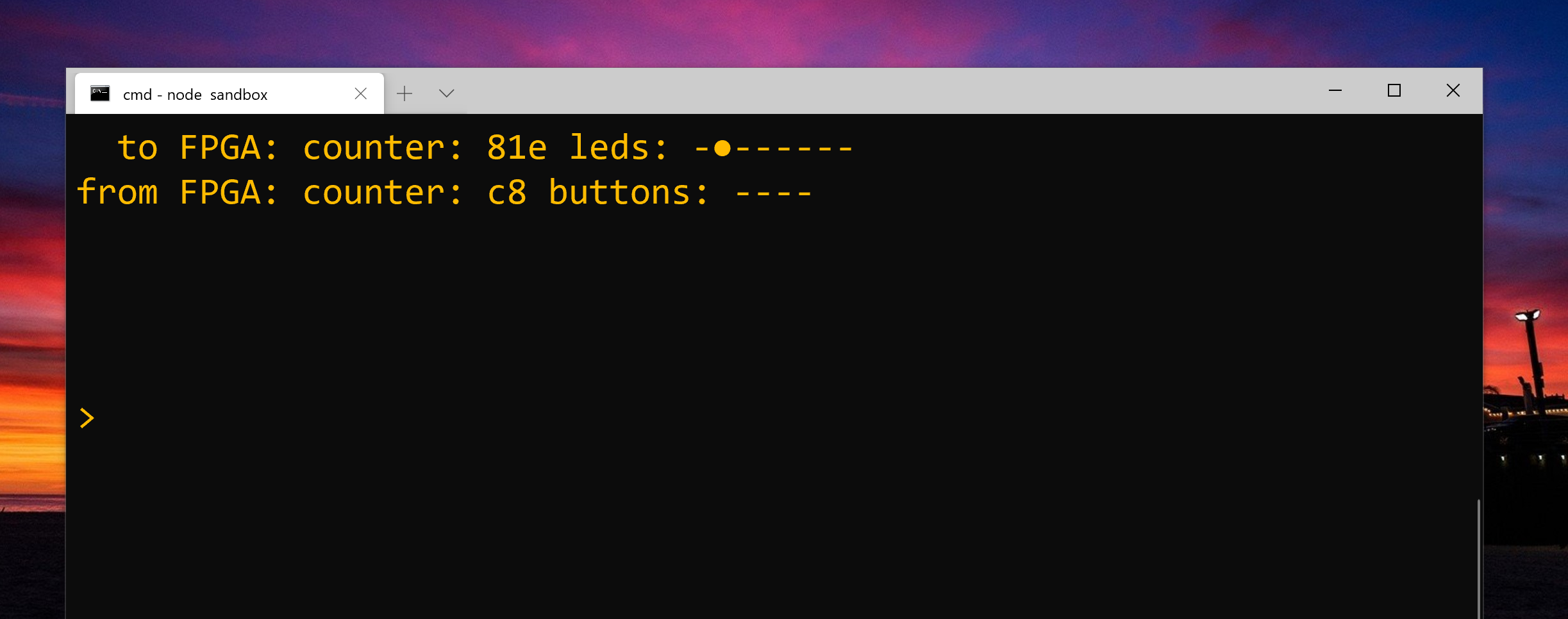
and here it is in action:
Wrote some #NodeJS bits and pieces to partner with the #FPGA reflector components I’ve been playing with. Makes it super easy to see signals from and send signals to the fpga via uart.
— Brad Robinson (@toptensoftware) January 18, 2020
JavaScript: https://t.co/wMkXjqa8lx
VHDL : https://t.co/Pp1RQDkqhN pic.twitter.com/q0PAsx9stH
VCD File Generation
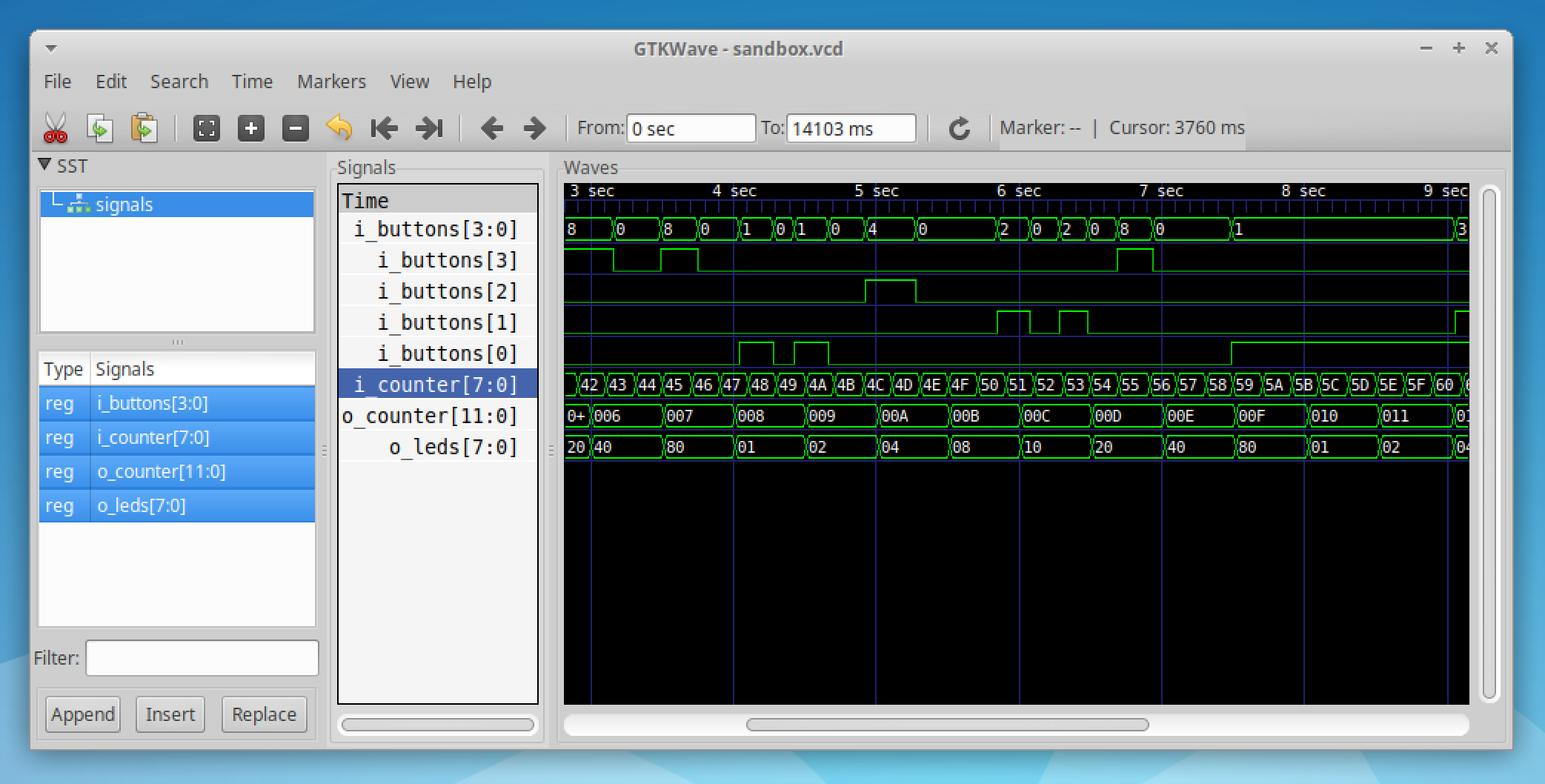
As mentioned above, the Reflector component can also generate a .vcd file that can be loaded by programs like GtkWave to see the signal values as they changed over time.
I'm not sure how useful this is in practice since the resolution is only millisecond(ish) but seemed like it might be handy so I took the time to implement it:
I went to some lengths to ensure this feature doesn't impact performance too much by creating a raw binary dump of the bit packets while running and then performing the slower generation of the .vcd file once the Reflector is closed.
(If you see a .vcd.tmp file that will be temporary binary dump file and was probably left behind by an aborted run eg: stopping the script in a debugger or an exception being thrown).
To generate the .vcd file just set the vcdFile in the options object passed to the constructor. If you don't need or want the .vcd file leave the setting out.
My #fpga reflector gizmo can now write a .vcd file.
— Brad Robinson (@toptensoftware) January 18, 2020
Resolution is only to the millisecond so not sure how useful but we’ll see.
For perf reasons it records everything in a binary file while running and then produces the vcd at the end. pic.twitter.com/grMVxL5jKD
The Wire Protocol
You don't need to understand the serial wire protocol to make use of Reflector, but you might like to write your own client side library (perhaps you prefer a different language to JavaScript/Node) or perhaps you want to use the Node library but need to implement your own FPGA logic.
The format is simple:
- Each packet starts with a byte with highest bit (ie: bit 7) set and the first 7-bits of transmitted data in the lower 7 bits.
- The remaining bits are transmitted 7-bits at a time in the following bytes with bit 7 in each of these bytes clear.
- The least significant bits are transmitted first
For example, suppose you're transmitting a 16-bit value declared as std_logic_vector(15 downto 0), it would be sent as take 3 bytes constructed as follows:
'1' & value(6 downto 0)'0' & value(13 downto 7)'0' & "00000" value (15 downto 14)
In Practice
I haven't had Reflector working long enough to know for sure how well it works in practice. While I probably wouldn't bother writing this for a one-off diagnostic situation it seems like a handy utility that I might use now that it's in the toolkit ready to go.
What do you think? Let me know on Twitter.