
Getting Started
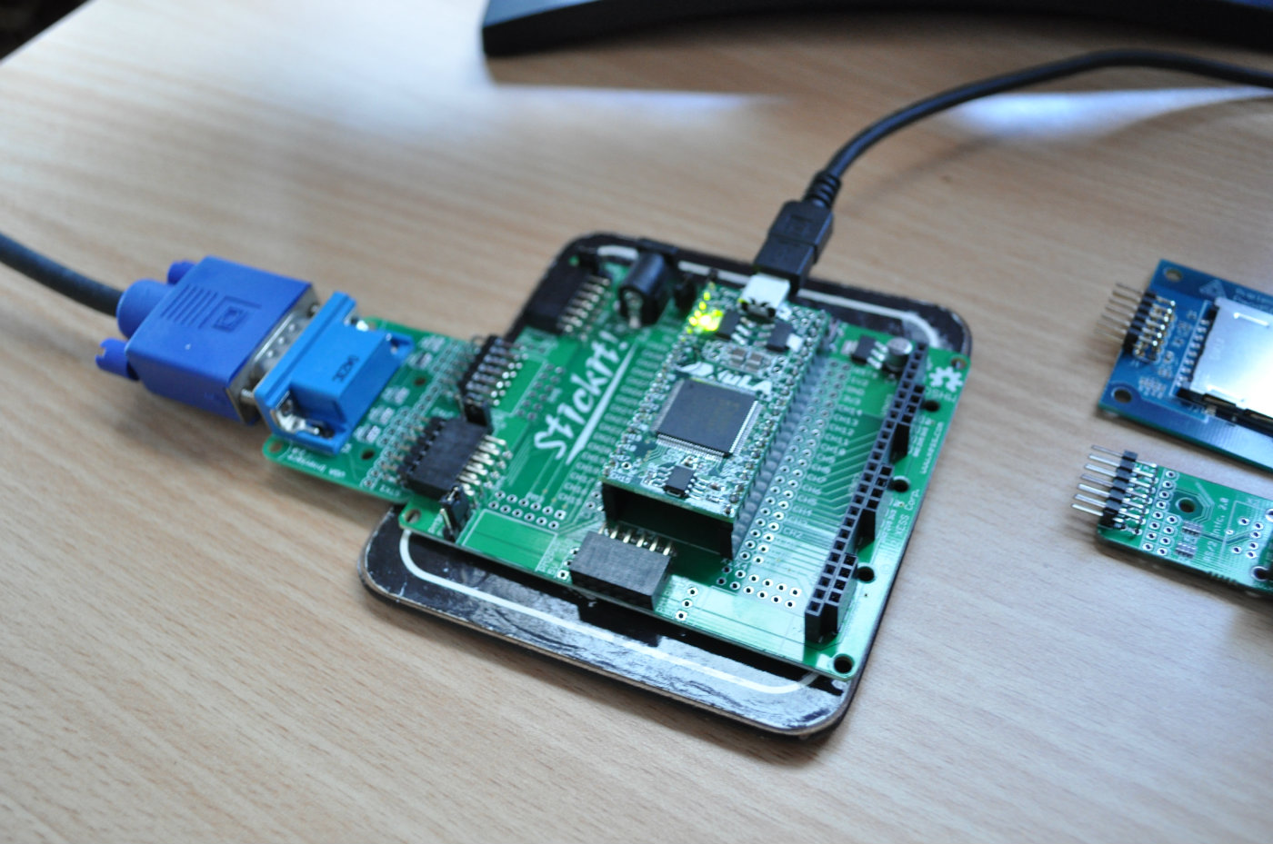
Over the last few days I've been learning my way around the tiny XuLA board, starting with soldering headers into the XuLA, some voltage selector jumpers for the Pmod connectors on the Stick-It board and setting up the VGA and PS2 connectors:
The Basics
Next I followed along with Xess's excellent getting started guide: FPGAs - Now What. It seems the "Hello World" of FPGA's is the blinking LED but since I couldn't be bothered setting up a breadboard, I went straight for a simple VGA grid display, using the VGA timing component from FPGABee.
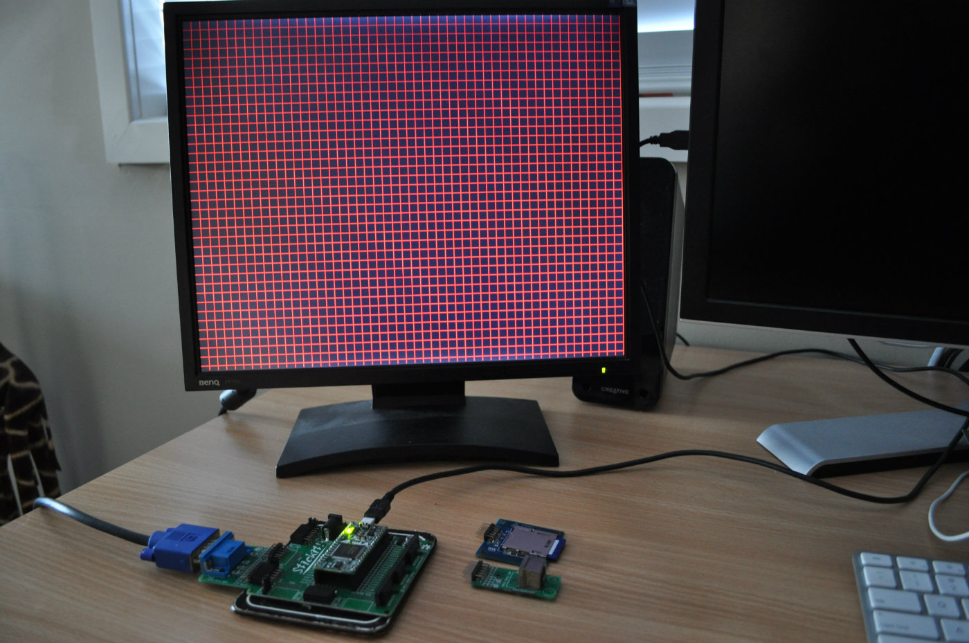
The main difference here compared to the Spartan 6 is the way the clock management is setup, but it turned out fairly simple to get a 40Mhz clock (required for an 800x600 display) from the XuLA's 12Mhz clock
--  12Mhz * 10 / 3 = 40Mhz
DCM_SP_inst_40_000 : DCM_SP
generic map
(
	CLKFX_DIVIDE => 3,
	CLKFX_MULTIPLY => 10
)
port map
(
	CLKFX => clock_40_000,
	CLKIN => clock,
	RST => '0'
);
Status Panel
With no LED's or 7-segment display on the XuLA I got to thinking about how I can get some insight into what's happening on the board for debugging purposes. On the Nexys-3 I routinely used these on-board displays for rudimentary debugging and while it's not ideal and it can be tedious it does get the job done.
In the book mentioned above, Dave Vandenbout describes a set of tools for monitoring the internals of the FPGA via the JTag port and some Python scripts. It looks to be a very flexible system which I'll probably look into more closely at some point. For the moment though I decided to implement a simple on-screen status panel consisting of 8 LED indicators and an 8 digit HEX display. It's fairly basic, but I'm sure will prove useful:
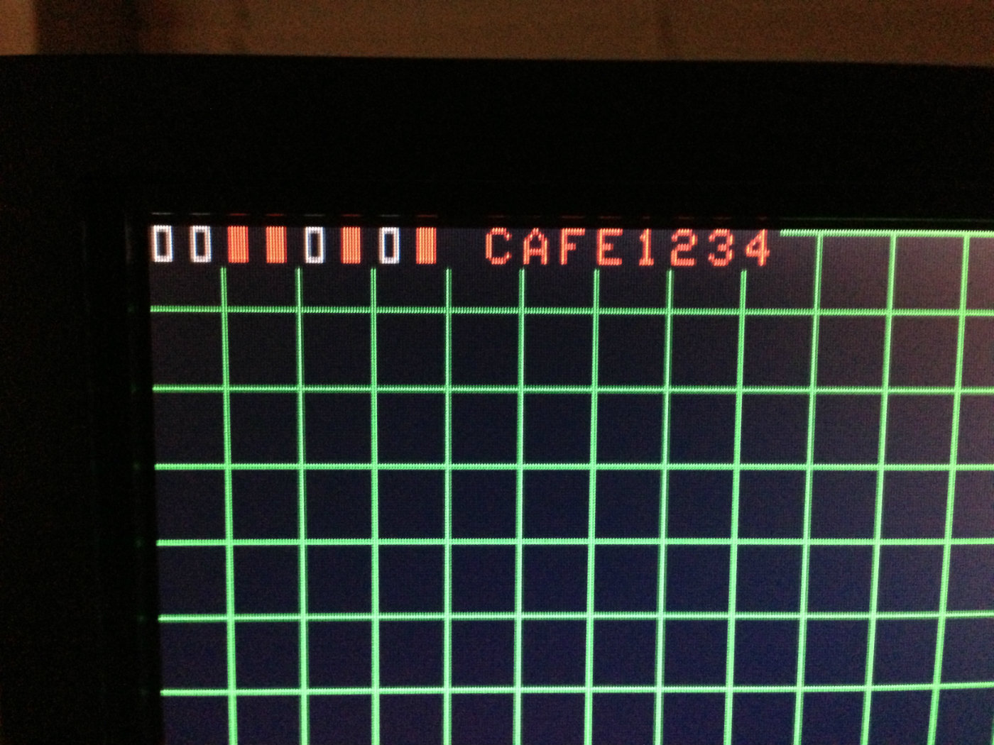
So far so good!
Next I think I'll look into getting a keyboard working via the PS2 connector.